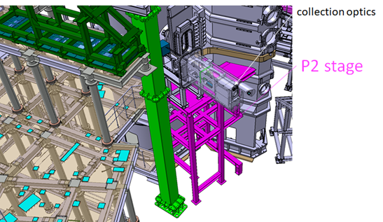
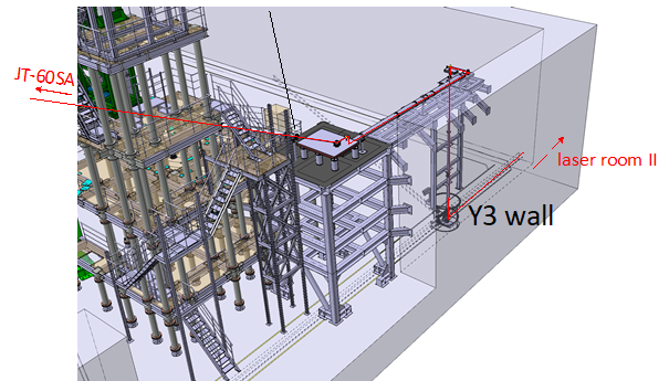
The YAG laser Thomson scattering system consists of core system installed at P2 horizontal port and edge system installed at P1 lower oblique port. Figures 1 and 2 show the schematic of P2 stage and Y3 laser stage for Thomson scattering, respectively. These stages are designed to keep the same stiffness as the stage used in JT-60U.
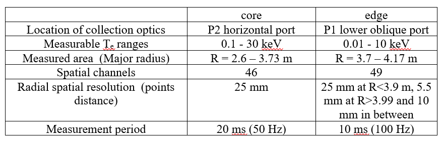
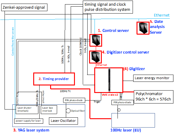
Figures 3 shows the data acquisition system and the laser control system. Two YAG lasers are fired synchronized with the timing provided by timing provider. Scattered lights by plasma are transferred to laser room II by bundled fibers and then fed to polychromators. In Figures 3, 96 polychromators are procured by F4E and components with number (1~5) are procured by QST. Output signals from polychromators (6 outputs for each measured point) are acquired by digitizers. Each digitizer has 32 ch inputs, and 19 digitizers are prepared where 10 digitizers are prepared for edge system and 9 digitizers are prepared for core system. The target specifications of the core Thomson scattering system are shown in Table 2.